8.2 Drawing and Interpreting Organic Formulas
Learning Objectives
- Understand different ways of presenting organic molecules.
- Comprehend different bonding patterns in organic molecules.
- Draw and interpret organic molecules using structural formulas, condensed structural formulas and line bond structures.
Drawing Conventions
Organic molecules can be large and can contain multiple atoms of carbon, hydrogen and other elements. Their architecture can be complicated, with chains of various lengths and ring structures.
Consider the structures shown here:
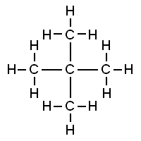
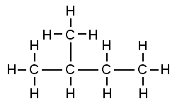
Both of these structures are representations of organic molecules. Each contains 5 carbon atoms and 12 hydrogen atoms. But they look different, and the properties of these substances are similar but not exactly the same.
The substance to the left has a boiling point of 9.5 ºC, making it a gas at room temperature. The substance to the right has a boiling point of 28 ºC, so it is a liquid at room temperature.
As we begin to consider and study organic molecules, we are very quickly faced with this fact: molecular structures (showing the number and types of atoms in a molecule, such as [latex]\ce{H_{2}O}[/latex]) are inadequate to describe these substances.
In organic chemistry, we make use of different types of formulas for this reason. There are several types, including:
- Structural formulas: which show every atom with its elemental symbol and every bond drawn as a line. These look a lot like the Lewis Structures you learned to draw in Chapter 3, but without the nonbonding electron pairs. Figure 8.2.1 shows an example of a structural formula.

- Condensed structural formulas: similar to structural formulas but without bonds shown to hydrogen atoms, so a carbon with 3 hydrogens attached becomes a [latex]\ce{CH_{3}}[/latex]. There are various levels of condensed structural formulas, and there are some rules about how formulas are properly condensed. The condensed formula of the molecule comprised of three carbons and eight hydrogens is shown below.
[latex]\ce{CH_{3}CH_{2}CH_{3}}[/latex]
- Line-bond, also called skeletal structures: these are the hardest to learn but the quickest to draw among those described here. They are used extensively in chemical communication. In line-bond structures, all bonds between carbons and between carbons and other atoms except hydrogen are shown as displayed in Figure 8.2.2. Hydrogens are not included unless they are attached to something other than carbon. The carbon atoms are shown without the elemental symbol. Instead, the viewer recognises carbon as present anywhere there is a vertex (pointed place) in the drawing and at the end of a line.

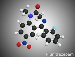
- Ball-and-stick model: the ball-and-stick model is a molecular model used in chemistry to represent the three-dimensional arrangement of atoms in a molecule. In this model, atoms are represented by spheres (balls), and chemical bonds between atoms are represented by sticks or rods, as shown in Figure 8.2.3. This helps to visualise the arrangement of atoms in a molecule and gain insights into the molecular geometry, bond angles, and overall structure.
- Dash-wedge structures: these structures are a common way to represent the three-dimensional arrangement of atoms in a molecule on a two-dimensional surface, such as paper or a computer screen. These structures use lines (dashes and wedges) to indicate the orientation of bonds in three-dimensional space, as shown in Figure 8.2.4. A dash is used to represent a bond that extends away from the viewer, going into the plane of the paper or screen. It suggests that the atom at the end of the bond is situated behind the plane of the paper. A wedge is used to represent a bond that comes out of the plane of the paper or screen toward the viewer. It suggests that the atom at the end of the bond is closer to the viewer.

Examples 8.2.1
Test Yourself
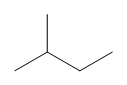
Can you tell which of the two structures is shown in the examples here?
a) [latex]\ce{CH_{3}CH(CH_{3})CH_{2}CH_{3}}[/latex]
b)
Answers
a) Condensed structural formula
b) Line bond/skeletal structures
Common bonding patterns in organic structures
Drawing structural formulas is a good starting point for a novice organic chemist. This works when dealing with small, simple structures, but when you start dealing with larger structures, it becomes increasingly difficult and time-consuming. Imagine trying to draw all atoms and bond every time you want to discuss the structure below (Figure 8.2.5), which is one small piece of DNA:

Large molecules such as this are commonly considered in organic chemistry and biochemistry. In these situations, line-bond structures really help. To get good at drawing them accurately, you will first want to get familiar with some common bonding arrangements involving elements frequently found in organic molecules.
- Let’s start with carbon. Carbon is said to be tetravalent, meaning that it tends to form four bonds. If you look at a variety of structures, including carbon, you can see that nearly always, each carbon atom has four bonding pairs of electrons, each represented as a line surrounding it (Figure 8.2.6).

This is a pattern that holds throughout most of the organic molecules we will see.
If carbon has other electron arrangements in its valence shell (in other words, if it does not fulfil the octet rule), it will have a formal charge or exist as a radical, as shown in Figure 8.2.8:

If you are able to quickly recognise these patterns (and the patterns described below for other atoms), it will help you tremendously as you learn more about organic chemistry.
- The pattern for hydrogen is easy: hydrogen atoms have only one bond and no formal charge. As a rule, all hydrogen atoms in organic molecules have one bond and no formal charge.
- For oxygen, you will see the atom bonding in three ways, as shown in Figure 8.2.9, all of which fulfil the octet rule.

In most cases, an oxygen atom has two bonds and two lone pairs, as it does in water. In this arrangement, it will have a formal charge of zero. If it has one bond and three lone pairs, as in the hydroxide ion, it will have a formal charge of -1. If it has three bonds and one lone pair, it will have a formal charge of +1.
There are, again, some additional possibilities. However, these three examples will account for virtually everything we see.
- Nitrogen has two major bonding patterns, both of which fulfil the octet rule, as shown below in Figure 8.2.10:

If nitrogen has three bonds and a lone pair, it has a formal charge of zero. If it has four bonds (and no lone pair), it has a formal charge of +1. In a fairly uncommon bonding pattern, negatively charged nitrogen has two bonds and two lone pairs.
- The third-row elements are commonly found in important organic molecules: sulphur and phosphorus. Although both of these elements have other bonding patterns that are relevant in laboratory chemistry, in a biological context, sulphur almost always follows the same bonding/formal charge pattern as oxygen, while phosphorus is present in the form of phosphate ion ([latex]\ce{PO_{4}^{3-}}[/latex]) (see Figure 8.2.11), where it has five bonds (almost always to oxygen), no lone pairs, and a formal charge of zero. Remember that atoms of elements in the third row and below in the periodic table have ‘expanded valence shells’ with d orbitals available for bonding, and the octet rule does not always apply.

- Finally, the halogens (fluorine, chlorine, bromine, and iodine) are very important in laboratory and medicinal organic chemistry but are less common in naturally occurring organic molecules. Halogens in organic compounds are usually seen with one bond, three lone pairs, and a formal charge of zero. Sometimes, especially in the case of bromine, we will encounter reactive species in which the halogen has two bonds (usually in a three-membered ring), two lone pairs, and a formal charge of +1. Common bonding patterns of halogens are shown below in Figure 8.2.12.

Organic structure types often do not include lone pairs since you can assume that the proper number of electrons are present around each atom to match the indicated formal charge (or lack thereof). Occasionally, though, lone pairs are drawn if doing so helps to make an explanation more clear.
Using the ‘Line Bond Structure’ Convention
In organic chemistry, the way compounds are drawn is somewhat different from the Lewis Structures you are used to seeing in your general chemistry. In some sources, you will see condensed structures for smaller molecules instead of full structural formulas that include every bond, as shown in Figure 8.2.13.

More commonly, organic and biological chemists use an abbreviated drawing convention called line-bond structures, also sometimes called skeletal structures. The convention makes it easier to draw molecules, but the convention does need to be learned.
Some considerations are:
- Carbon atoms are not depicted with their elemental symbol but rather by a vertex (corner) or a free end of a bond.
- Open-chain molecules are usually drawn out in a ‘zig-zig’ shape.
- Hydrogens attached to carbons are generally not shown; rather, like lone pairs, it is assumed the person viewing the structure knows where they are.
- Hydrogens bonded to nitrogen, oxygen, sulphur, or anything other than carbon are shown but are usually drawn without showing the bond.
The following examples illustrate the convention ( Figure 8.2.14).

Line-bond structures make it much easier to see the basic structure of the molecule and the locations where there is something other than [latex]\ce{C-C}[/latex] and [latex]\ce{C-H}[/latex] single bonds. It can also be drawn quickly.
Sometimes, one or more carbon atoms in a line structure will be depicted with a capital C if doing so makes an explanation easier to follow. If you label a carbon with a C, you also must draw in the hydrogens for that carbon.
Key Takeaways
- Organic molecules can be represented in different ways.
- Understanding the common bonding patterns of common atoms found in organic chemistry is essential for drawing and interpreting organic structures.
- The line bond structure is the commonly used method to represent organic molecules.
Exercises
Practice Questions
A good way to test your understanding of the line structure convention is to see if you can accurately determine the number of hydrogen atoms in a molecule from its line structure. Do this for the structures here.
How many hydrogens are bonded to carbon at each hotspot (identified with a purple plus sign) on the structure shown below? Click on the purple spot to find the correct answer.
Media Attributions
An atom having four covalent bonds.
